In this tutorial, we investigate the numerical simulation of reinforced brick masonry beams using GFRP (Glass Fiber Reinforced Polymer) reinforcement in Abaqus.
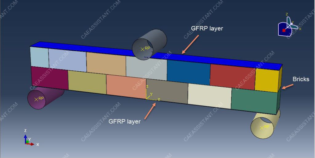
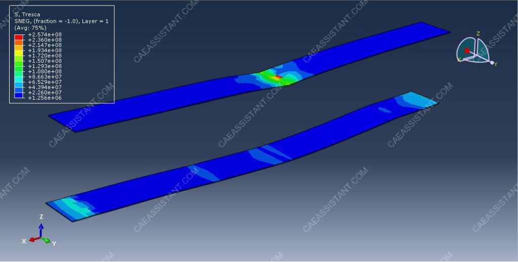
The bricks are modeled as three-dimensional solid parts, while the GFRP sheets are modeled as three-dimensional shell parts. A figure of the assembled parts is shown below.
Natural stone structures make up a large portion of the world’s architectural heritage, including bridges, civil buildings, places of worship, and historical monuments. Stone is widely used due to its beauty, availability, hardness, durability, strength, and sustainability. Understanding the mechanical behavior of stone structures is essential. These structures typically have high compressive strength but very low tensile strength, especially at the joints. As a result, stone is mainly used in compression-dominated members in historical buildings.
Reinforcing masonry structures is a common practice in the restoration of historical buildings to improve their structural resistance. Reinforcement methods include the use of steel bars, rings, and composite materials. In recent decades, composite materials such as FRP have gained popularity for strengthening both modern and historic masonry due to their high tensile strength, corrosion resistance, and ease of application. Many studies have explored the use of carbon and glass fiber-reinforced composites for this purpose.
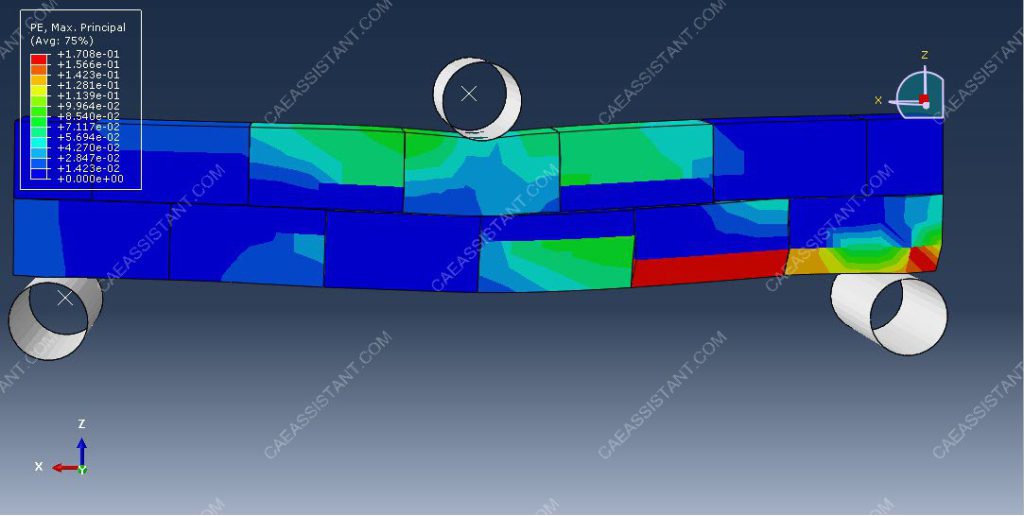
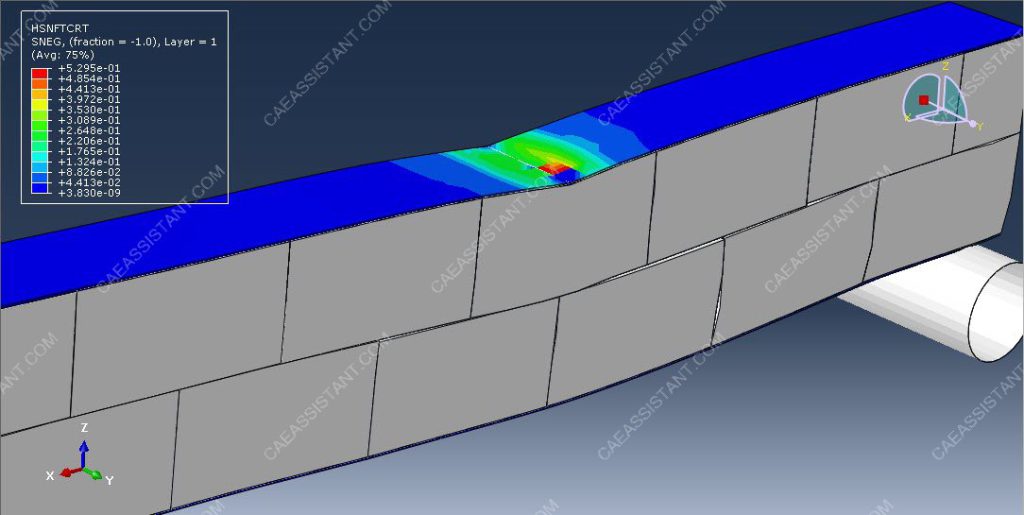
In the simulation, the bricks are assigned elastic behavior using the Concrete Damaged Plasticity model. The GFRP sheets are defined with elastic lamina behavior and Hashin’s damage criterion. The analysis uses an explicit step with general contact. A perfect contact is assumed between the masonry blocks and the GFRP sheets. Mortar is modeled using cohesive surface interaction, incorporating cohesive behavior and damage parameters.
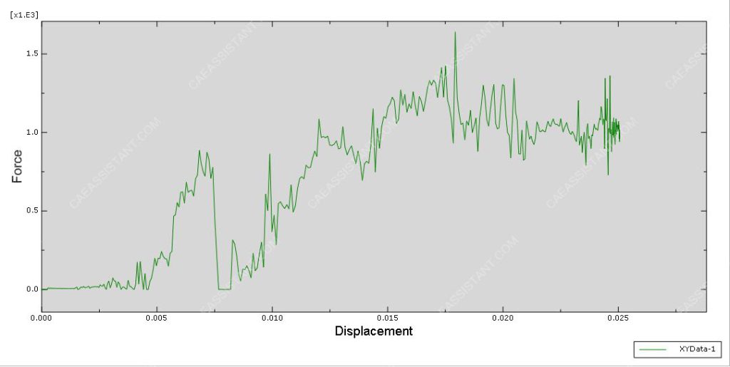
Boundary conditions include a fixed constraint at the bottom rigid bodies and a displacement-controlled load applied to the top rigid body. A fine mesh is recommended to ensure accurate results.
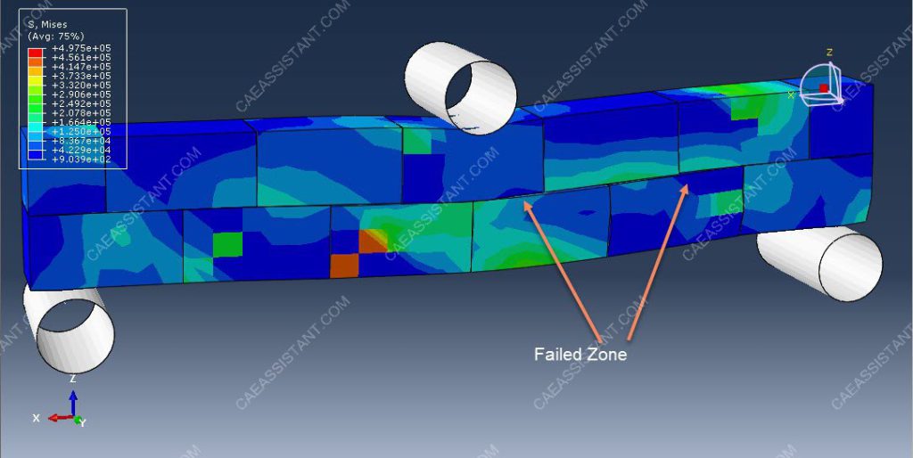
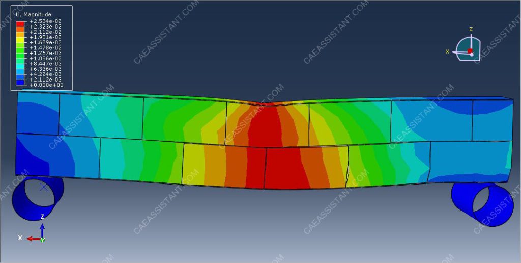
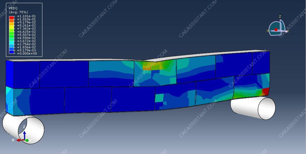
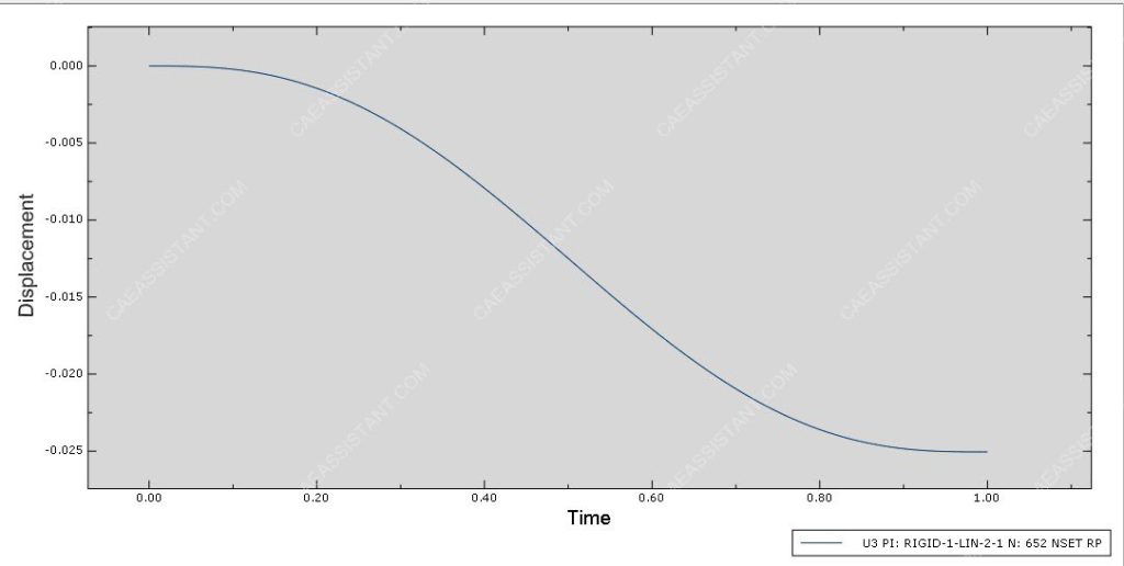
After running the simulation, results such as stress, strain, and displacement can be extracted. Sample result figures are provided below.